
In this tutorial we are going to show how to use the PiSoC as a Labview Linx device. This will let you interact with digital and analog IO inside of the labview interface. This project was designed by students from The Design Lab at Rensselaer.
Install
You’ll need to program or bootload your PiSoC+ with this firmware on our github. You can learn how to do that in our PSoC Creator tutorial. While the provided firmware is compiled for PiSoC+, it can be used on the PiSoC by changing the device in the PSoC Creator device selector, which is also explained at the bottom of the PSoC Creator tutorial.
Software
This was tested on Labview 2015, but it should work on the past few year’s versions.
Install Linx (Via the package manager, it should open up when you hit download)
Install NI VISA
You should be all set!
Examples
First we’ll start with a two simple example projects to explain how to use PiSoC with Linx. Plug your PiSoC into your computer, it should pop up as “PiSoC USB UART” in Windows when you plug it in. For Windows, if you haven’t already, you’ll need to install our PiSoC USB Driver.
Open up Labview, and click on the “Open Existing” button. We’ll be looking for some example Linx projects. On Windows they can be found in C:\Program Files (x86)\National Instruments\LabVIEW 2015\examples\MakerHub\LINX.
Blinky
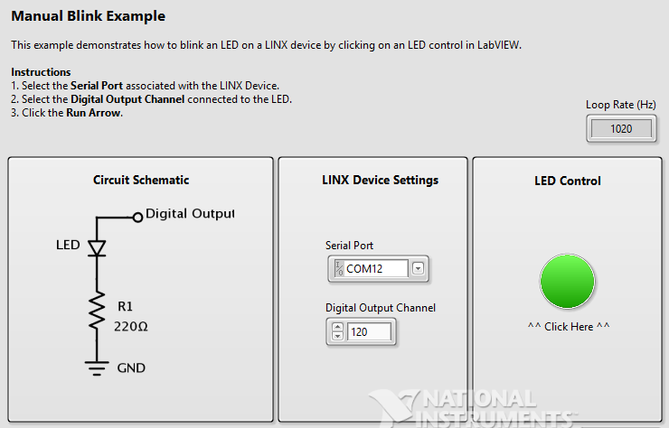
In this example we will blink the onboard PiSoC LED. Open up the “LINX – Blink (Simple).vi” File.
The first thing you’ll need to do is select which Serial Port the PiSoC is on. When you click the drop-down menu there might only be one choice, in which case it is probably the PiSoC. You can also open up device manager in Windows and expand the ports drop-down menu to find out which Com Port the PiSoC is on.
Now try running the project. It will complain that the digital output channel was not a valid choice, and then list all valid digital pin choices. The digits correspond to a PSoC pin number. So for example, you can change it to “120” (P12.0), which is the location of the PiSoC onboard LED. Once you change it try running the project again, and then wait a few seconds. You should be able to click on the LED Control button to blink the LED on and off.
Analog Read
Click on and open the “LINX – Analog Read 1 Channel.vi” project. This project will display the voltage on Pin 3.0 of the PiSoC.
Set your Com Port as before, and then run the project. Make sure the Analog AI (Analog Input) channel is set to 1 or you’ll get an error when you try to run it. Go ahead and try to run it now by clicking on the run arrow near the top. After a few seconds you should see the graph moving with the voltage value.
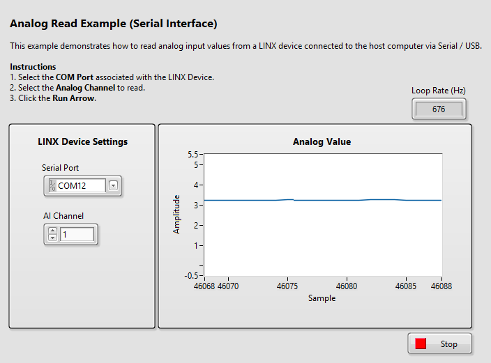
I used a wire to connect P3.0 to the 3.3V line on the PiSoC
Try plugging a wire into different things on the board (5V, 3.3V, GND) to see how it changes.
Analog Write
You’ll need to open the example from our github page. Analog out requires additional setup that is done for you in the example because it isn’t fully supported in Linx. This is mostly because most devices don’t have DACs, unlike our trusty PSoC. Follow the same instructions as in the Analog Read example above, and then set the AO channel to 1.
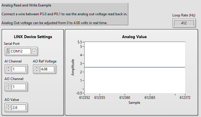
Use a wire to connect P3.0 (Analog In) to P0.1 (Analog Out). Then run the example. You should be able to change the AO Value and see that reflected in the Analog Value graph.
Further Usage
You have access to Digital IO, Analog IO, and PWM functions.
Analog Input (AI) 1-8 corresponds to P3.0 through P3.7
Analog Output (AO) 1 corresponds to P0.1
PWM (50Hz, set Duty Cycle only) 1-8 corresponds to P6.0 through P6.7
In general, I would recommend you make a copy of one of the Linx example projects and use that as a base for your own project. That way, all the initialization is handled for you.
As always if you need any help post a comment or email me.
T.Mastuda
February 21, 2017 at 9:04 pm
Dear Sir, Thank you very much for your works. I have a lot of interest in PSoC-LabVIEW works. So, I want to try your works, but on my CY8C5888LTI-LP097 (PSoC 5LP Prototyping KIT), not your CY8C5868AXI-LP035. I changed device in PSoC Creater, what I want one, but get some error messages. (Sorry, but I can not append error messagaes.PNG in this comment areas).
1: Bootloader does not much
2:EEPROM v2 10 contains error
then fitter aborted. (PSoC Dev. 3.3 and 5 are same results)
If you have any comment or suggestions, I am so glad. Thank you.
Robert Barron
February 23, 2017 at 7:08 pm
You can send me an email with any additional details or images: barron@embeditelectronics.com
As for your errors, I think you can try deleting those components and try to compile again. You won’t need the bootloader since you program that kit over SWD unlike the PiSoC. I’ll take a look at why the eeprom no longer works this weekend and get back to you. Thanks, Robert
Robert Barron
March 2, 2017 at 8:49 pm
For anyone else having problems getting this project to compile in new PSoC Creator versions or for a different PSoC 5 kit, here’s what I did to fix it:
1. Go to Project->Update Components. This will fix your eeprom component problem
2. Delete the bootloadable component if you aren’t bootloading your board (IE. You are using the PSoC 5LP Prototyping KIT or a miniprog for programming) You won’t need it for those kits.
3. Delete 8 GPIO pins (1 port) in the GPIO tab if you are using a board with less IO than the PiSoC, such as the PSoC 5LP Prototyping KIT.
T.Mastuda
March 15, 2017 at 3:21 am
Thank you for a great works and suggestions.
sarika
April 11, 2017 at 1:21 am
Thanks for this post! I’m still a learner on this technology, this info seems to be really helpful. Thanks again!