In this one we will making your own PSoC programmer called the KitProg for about $20. A little bit of soldering is recommended, but not strictly required. This programmer will allow you debug PSoC 4 and 5LP devices, including the PiSoC! As a reminder, you can always USB bootload the PiSoC, which allows programming without this device or the Miniprog, but a full programmer device gives you more flexibility including debugging. If you have a Miniprog 3 you also don’t need this device.
Parts
CY8CKIT-059 – This is a $10 PSoC 5LP dev kit and PSoC programmer. We’ll be snapping off the programmer side of it.
5 Position Female Receptacle Connector – This is a female header that connects to the programming header on the PiSoC.
USB 2.0 Cable A Female to A Male (Optional) – USB extension cable to make it easier to use the programmer.
5 Position Male Receptacle Connector (Optional) – You can put this header on the PSoC dev kit side of the CY8CKIT so that you can still program that board after snapping off the programmer.
Assembly
Putting the whole thing together should only take a few minutes.
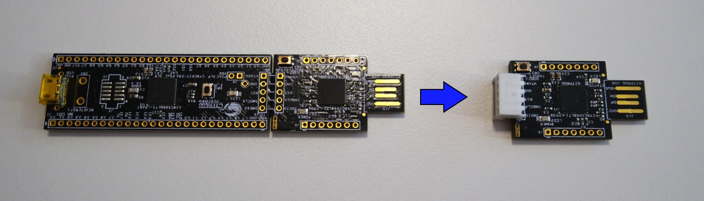
- Snap off the programmer board (the short side) from the main board on the CY8CKIT. You might have some traces come loose and stay connected between the boards. Try to cut them instead of ripping them further. The programmer should still be functional even if some of the traces come off.
- Solder the 5 position female header to the programmer board. If you are not comfortable soldering, you could always hold the connector in place when you try to program. This is a great opportunity to learn how to solder though.
- This one’s optional. Solder the 5 Position male header to the main board of the CY8CKIT. You never know when you might want to use it.
That’s it! It should look like the picture below. Lets try plugging it in next.
Usage
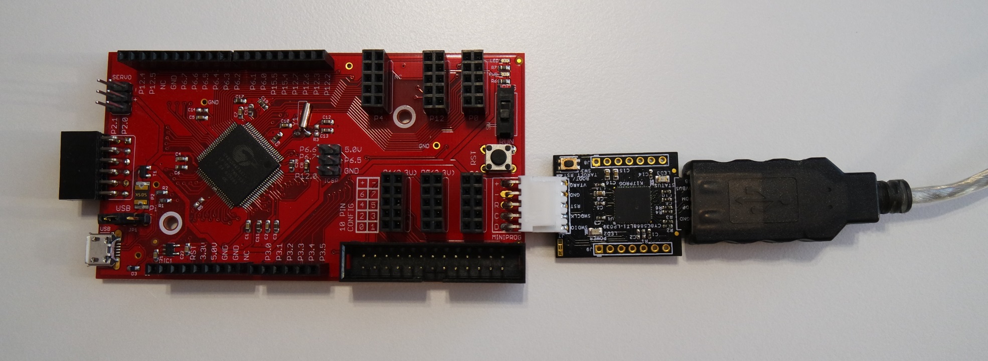
Plug your newly made KitProg programming board into the PiSoC Prog header. Then either plug it into your USB extension cable, or directly into the computer. If you are plugging directly into the computer, look at the pins in your USB port to figure out what orientation the programmer needs to go. Windows should automatically install the KitProg drivers.
Download my example PSoC Creator project or make your own. This example blinks the onboard PiSoC LED. Unzip and open up the project in PSoC Creator.
Try programming the PiSoC (Debug->Program) the with this example. You should see the LED blinking. You can play around with how fast it blinks by following the instructions in the TopDesign (schematic) or main.c (code) files. You can also try Debugging (Debug->Debug) the code. You might want to add a variable that increments in the for loop so you can watch it change in the debugging mode.
Troubleshooting
If you can’t manage to program your PiSoC and the select debug target window comes up, there could be a few causes.
- Check your five solder joints to make sure they are really connected. You could do a continuity check with a multimeter if you have one.
- Make sure Windows installed the driver for your kitprog. You should see it listed in the select debug target window.