Here you can find more information about the technical aspects of the PiSoC and PiSoC+. Below is the pin out for the Python and Scratch API. If you use PSoC Creator you can configure most of the pins for any function.
There is a controllable LED on P[12]0. The prog/run switch can also be used in your applications, and is on P[15]0. The USB/PI jumper is used to select whether the PiSoC is powered using USB or over the Raspberry Pi header.
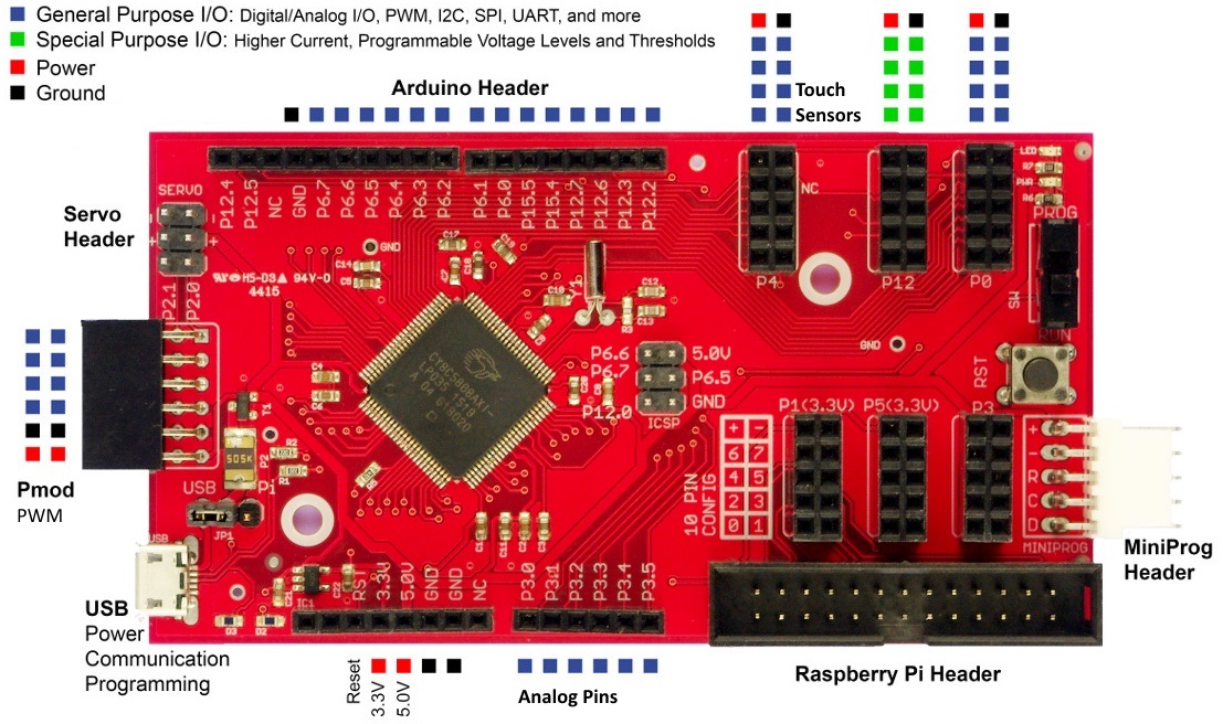
Scratch and Python API pin out
PiSoC utilizes Cypress Semiconductor’s PSoC 5LP CY8C5467AXI-LP108 (Datasheet), a programmable system on a chip, which combines a micro controller, programmable analog and digital logic in one chip. It has an ARM Cortex M3 CPU with 128KB of flash. Our board can be used as a standalone microcontroller, a data acquisition/instrumentation device, or in conjunction with the Raspberry Pi or your PC as a hardware accessory. This opens up endless possibilities! Not to mention that PSoC is used in many commercial products, ensuring a reliability most other chips cannot commit to.
PiSoC+ uses the PSoC 5LP CY8C5868AXI-LP035 (Datasheet), which adds more power in the form of a Delta Sigma 20bit ADC, an extra 12bit SAR ADC, two more DACs, and 256KB of Flash. If you don’t know what any of this means, the regular PiSoC already has more features than nearly all other development boards (reconfigurable pins and programmable analog and digital logic!), so you won’t be left wanting.
When you use PSoC Creator, you will have to choose one of the above PSoC 5LP chips in your project. Most projects will be able to compile for either, and it will let you know what resources are available in the Resource Meter.
- To choose your device in PSoC Creator, go to Project->Device Selector. When in the device selector you can narrow down the selection to just PSoC 5 by leaving only ARM CM3 selected in the CPU tab.
- To see what resources you have available to use in your project, go to View->Resource Meter.
Roy Volkwyn
October 14, 2016 at 7:02 am
PiSoC is a great product!
I wanted to standardize on PSoC5, but the range of PSoC 5 deveopment boards from Cypress is extremely limited at present. I cannot justify the development cost and time of developing my own PSoC 5 board.
The Sparkfun FreeSoC2 (Dev-13229) is another excellent PSoC 5 development board, but it lacks PiSoc’s Raspberry Pi interface.
For me, the reasons for choosing PiSoC for my next embedded project are:
– Raspberry Pi interface
– Python and Scratch downloable from the vendor’s website
– Labview Linx downloable from the vendor’s website
Would have been nice if PiSoC had two more headers to accommodate one Mikrobus “Click” board.
It seems as though a Mikobus Click shield for the Arduino Uno would enable a PiSoC to accommodate a Click board, or two Click boards to be exact.
http://www.mikroe.com/click/arduino-uno-shield/
I have bought one Click board that cost approximately half the cost of PiSoC+ plus $15 shipping cost to my country. I may also purchase a WiFi Click board. Hence being able to use Click boards with PiSoC is important for me.
Roy
Robert Barron
October 18, 2016 at 7:07 pm
Hi Roy,
Thanks for the message, I definitely agree with you on the current landscape of development boards. In terms of WiFi, the easiest solution would be to use a Raspberry Pi for your internet access while connected to the PiSoC. If you need it to be lower power it should be possible to use an Arduino shield, Pmod module, or a Click (with the Click Uno Shield) module like you suggested. However, you will need to do some coding in PSoC Creator to get any of those implemented. It is completely possible to interface with them in Python by extending our PiSoC Python API on PSoC Creator.
Electrically, the modules need to have 5V tolerant I/O if using the Arduino headers in order to work. The PiSoC will provide the Click Uno Shield with 5V and 3.3V power, but the I/O on the pins are 5V. The PiSoC does have two sets of 3.3V I/O (P1 and P5) that could also be used without issue. If you’re interested I could take a look at easy it would be to make a simple adapter board for Click, but I would still suggest making use of Pmod and Arduino headers already on the board.
Thanks!
Robert
Roy Volkwyn
October 21, 2016 at 5:22 am
I just learned now that the only some of the Pi 1 models use 26 pin GPIO connectors. All the rest use 40 pin GPIO connectors. http://www.raspberrypi-spy.co.uk/2012/06/simple-guide-to-the-rpi-gpio-header-and-pins/
Fortunately, some companies make 26 pin to 40 pin adaptors (basically with only 26 way cable) so one can interface a Pi with a 40 way GPIO to a board with only a 26 pin interface.
Robert Barron
October 24, 2016 at 6:27 pm
The 26 pin to 40 pin adapter does work fine with the PiSoC. I’ve personally used this one from Adafruit on the Pi 2 and 3.