First off, here is a video demonstration of Scratch.
It goes through the creation of a Scratch program that utilizes the RPiSoC’s analog functionality. I then go one step further and create a simple two player game out of it. For this post I thought I’d give a detailed explanation of all the Scratch blocks used in the video.
First you need to install the following things:
1. First you need our psoc_2_pi Python API set up. (SPI support only for now) Instructions here: http://embeditelectronics.github.io/psoc_2_pi/getting_started.html#download-the-python-files-from-git
2. Next you need to install Scratch GPIO: http://cymplecy.wordpress.com/scratchgpio/scratch-raspberrypi-gpio/
3. Finally download this repository: https://github.com/EmbeditElectronics/scratch OR
git clone git://github.com/EmbeditElectronics/scratch.git
and put the files into the scratchgpio5 folder, overwriting any existing files. The path will should be /home/pi/scratchgpio5
There are example projects included. You can open those up or continue on.
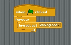
analog read
Our first few blocks are pretty straightforward. When the green flag is clicked the program will start. The “forever” block simply loops whatever is inside it forever. So, it will send the analog read broadcast forever. What the “broadcast” does is send a message to the RPiSoC, telling it to begin reading analog values on a pin. In our case this is the default analog pin which is hooked up to a potentiometer. This potentiometer serves as a sort of knob. As it is spun the voltage will change (in a range of 0v to 5v) as shown in the video.
In the future there will be other broadcast keywords besides analogread. In fact, any function available in our python API will eventually be available. This is thanks to the fact that we are using ScratchGPIO , which we have expanded to include our board.
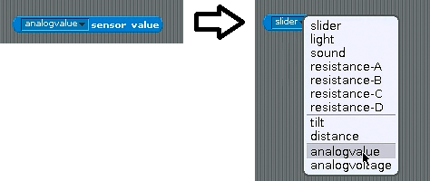
analog reading
Next we have the sensor value block. This block lets you read values from a predetermined list of sensors. We have made our analog sensor available to be read. The analog value is a 16-bit digital number corresponding to the voltage (between 0 and 65535, which corresponds to voltages between 0v and 5v). In the next part I will show why we want the number instead of the voltage.
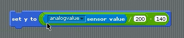
Setting the y-axis value

Scratch on the x-y grid
Here is a combination of several blocks. “Set y to” sets the y coordinate of Scratch the cat, who is bound to an x-y grid. This grid goes from -240 to 240 on the x-axis, and -180 to 180 on the y-axis.
The rest of the blocks read like an equation: y= (analogvalue/200) – 140.
Breaking this down we first have analogvalue/200. This is meant to map our analog value, which can range from 0 to 65535 (the maximum of a 16-bit number) to the y-axis. The y-axis goes from -180 to 180, meaning it has 360 points on it.
So 65535/360 = 182. I choose to round this number up to 200 so the top and bottom of the cat did not get cut off (the center of his body seems to be his actual coordinate).
Then we have (analogvalue/200) – 140. The – 140 is simply there to center scratch on screen. That way a voltage of about 2.5 will equal 0 on the y-axis, centering the cat.
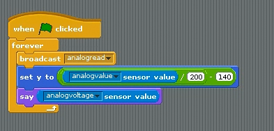
The finished program

Scratch the cat displaying the voltage
Finally we have the “say” block. This will make scratch (or any other sprite, there are plenty of others besides the cat) display the voltage.
The finished program will now move scratch as I turn the potentiometer.

Scratch dodging a cannonball
Next time I will go over how I made a simple two player game using analog input as a controller.